Recycling of Blast Furnace Sludge –
Best Available Technology
Summary
Almost all the iron and steel manufactured in the world is made from pig iron produced in blast furnaces (BF). However, the dust and especially the sludge generated throughout this process, does represent a great challenge with respect to the overall sustainability of this highly material and energy intensive industry.
During the production of pig iron in blast furnace, a Zn- and Pb-containing sludge is generated in the air pollution control system. More than ½ of the mass input becomes outputs in form of off-gas and solid wastes/by-products. This toxic waste can be landfilled after dewatering and pretreatment, which is very costly. The sludge particles contain large amounts of Fe and C that could be recycled in the furnace. However, the Zn content of the sludge is high, and the Zn input to the blast furnace must be limited, so in order to be able to reuse the sludge generated, the Zn has to be removed as much as possible (major portion concentrated in the <20 µm).
Over the years and on basis of his know-how in the field of wet mechanical treatment, AKW Equipment + Process Design has been able to develop the right process concepts able to solve the issue and generate a sludge with Zn content reduced, and thus reusable. There are however no standard plant concepts for a BF-sludge treatment plant, as each process design and plant arrangement will primarily depend on the nature of the feed sludge, and therefore will be based on pilot test work that are performed in AKW Equipment + Process Design technical laboratory.
On basis of the test results, the suitable and customized process solution can be developed, discussed and later on engineered and executed by AKW Equipment + Process Design. This unique process concept is presented in the following paper: multi-stages hydrocycloning, combined with thickening and filter pressing.
Introduction
Almost all the iron and steel manufactured in the world, is made from pig iron produced by the blast-furnace process.
A typical blast furnace consists of a cylindrical steel shell lined with refractory. The lower portion of the furnace, called the bosh, is equipped with several tubular openings through which the air blast is forced. Near the bottom of the bosh is a hole through which the molten pig iron flows when the furnace is untapped, and above this hole, is another hole for draining the slag. The top of the furnace contains vents for the escaping gases, and a pair of round hoppers closed with valves through which the charge is introduced into the furnace. Modern-day blast furnaces are operated in conjunction with basic oxygen furnaces; the molten pig iron is used to charge the steel furnaces.
According to the World Steel Association the total production of crude steel reached about 1,875 million tons in 2019, a 2,7% increase from 2018. The forecasts for 2020 and 2021 are showing further growth, to reach up to 1,952 million tons.
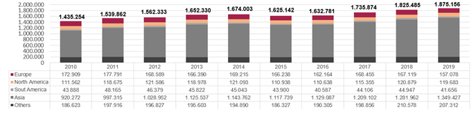
Table 1: EXTRACT: Total production of crude steel 2010 – 2019 (includes all qualities: carbon, stainless and other alloy) / World Steel Association [1]
The blast furnace is fed with steel, scrap, coke, spice metals, etc. The resulting exhaust air, which contains large amounts of contaminated dust, is dedusted by air-cycloning and then further cleaned in a wet scrubber. This produces the pitch-black material, the so-called sludge, which contains a lot of pollutants, such as zinc and lead and a large amount of carbon.
Blast Furnace Sludge Treatment: Purpose, Means and Results
The Iron and Steel industry is a highly material and energy intensive industry. More than ½ of the mass input becomes outputs in form of off-gases and solid wastes/by-products. The rate of reuse and recycling of solid wastes/by-products has been increased dramatically in the last 30 years. However, there are still considerable amounts disposed to landfills. Especially dust and sludges represent a great challenge, to improve the needed overall sustainability.
Looking at the European market only, for a total input (iron ore, scrap, coal, lime, limestone, fuel and gas, additives,…) in the range of 311 Mtons, the output as crude steel only amounts for 155 Mtons, the balance ending up as wastes.
The major sources of dust and sludge in the iron and steel industry originates from sinter plant, blast furnace (BF), based oxygen furnace (BOF) and Electric Arg Furnace (EAF). Looking at the Zn content, it is known that the major portion is concentrated in the < 20 µm fraction, hence where the focus must be put.
In the below tables the difference in the Zn content of the dry dedusted waste and the wet scrubber is shown. The wet scrubber sludge contains much more Zn and Pb per unit amount.
Dry dust composition:
| C | Fe | Pb | Zn | SiO2 | CaO | MgO | |
| (%) | 25-40 | 15-40 | 0.02-0.07 | 0.1-0.5 | 4-8 | 2-8 | 0.3-2 |
Table 2: Typical chemical composition of dry coarse dust, from BG-gas treatment (weight %)
Wet dust composition:
| C | Fe | Pb | Zn | SiO2 | CaO | MgO | |
|
(%) |
15-47 | 7-35 | 0.9-2.0 | 1-10 | 3-9 | 3.5-18 | 3.5-17 |
Table 3: Typical chemical composition of fine dust/sludge, from BF-gas treatment (weight %)
The fractional analysis shows that the pollutants accumulate in the fine fraction < 20 µm. This is due to the large specific surface area of the particles in this fraction, that attract most of the Zn pollution. The focus is therefore to remove this fine fraction.
| (mm) | -0.02 | 0.02-0.032 | 0.032-0.063 | 0.063-0.09 | 0.09-0.125 | 0.125-0.18 | 0.18-0.2 |
| Zn (%) | 2.82 | 0.64 | 0.28 | 0.21 | 0.14 | 0.18 | 0.08 |
Table 4: Overview fraction containing Zn
Resulting sludge treatment process
Recognizing that most of the unwanted Zn is concentrated in the fine fractions below 20 µm the task is to classify the sludge accordingly.
In combination with the classification process also the special sludge handling needs to be considered especial for the dewatering to result finally in material with low moisture content.
For this special application, the technology of AKW Equipment + Process Design has proven to be the suitable solution: multi-stages high performance hydrocycling, combined with thickening and the appropriate dewatering solution (selected on basis of the customer specifics).
The below typical flowsheet shows the process of separating of the reusable product fraction and concentrating the Zn portion in the fine fraction.
The process starts with the pre-screening to separate coarse lumps, followed by a multi-stage (typically 2) hydrocycloning process where the overflow into which the heavy metals have accumulated will be directed to the thickener for further up-concentrating, so that a further dewatering in filter press or chamber filter prepares for disposing. The underflow of the first stage of hydrocycloning will be directed after dilution to a second stage where the underflow generates the Zn reduced sludge that can be reused in the blast furnace.
This reduces the necessary landfill in a range of 50 to 80 %.
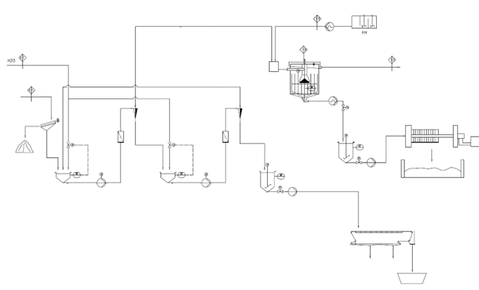
Pic 2: Typical flowsheet set up for a BF-sludge treatment plant, simplified
Briefly equipment description:
AKA-VORTEX hydrocyclones:
The conical hydrocyclone with its rotational flow generated by pump pressure, is a separation device which has been in use in process and preparation technologies for a long time. Its advantage is the capability to generate, within a limited footprint, highly efficient and fine cut size on a population of particles.
AKA-SET Thickeners:
The AKA-SET is a high performance thickener, available as flat or conical version, for process water clarification and slurry thickening. Macro flocs will be created due to the flow route of the flocculated feed slurry in counter-current to the sedimentating particles in the filtering zone. These flocs have the advantage of sedimenting at a higher rate than the micro flocs generated in the conventional thickeners. This results in a higher loading rate per unit settling area and smaller thickener diameters, compared to the traditional static thickeners.
Sludge dewatering:
Whether discontinuous chamber filter presses or belt filter presses will be used for dewatering the different sludge slurries, which are the Zn reduced sludge from the AKA-VORTEX cyclones or the Zn enriched sludge from the AKA-SET thickener.
This unique set-up, fully developed by AKW Equipment + Process Design, was already regarded by the European Commission as Best Available Technology (BAT), and is listed in its Integrated Pollution Prevention and Control Report.
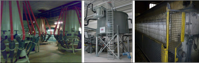 Pic 1: Illustration (1) Hydrocyclone Distributor AKA-SPIDER, equipped with hydrocyclones AKA-VORTEX, (2) High Performance Thickener AKA-SET, (3) Filter press AKA-PRESS
As there is no standard plant concept for a BF-sludge processing unit and the design and plant arrangement will primarily depend on the nature of the feed sludge, pilot test works are an important first step being able to determine the best process. AKW Equipment + Process Design’s technical laboratory and test center is equipped with the full range of process equipment, ensuring an effective test work and allowing the characterizing of almost all sort of processing steps. Combined with measurement capabilities (3D digital microscope, XRF system, laser particle size analyzer), comprehensive pilot tests can therefore be organized, fully handled out of one place, and allow to generate process flowsheets as well as the associated process performance guarantees.
In the following two examples of recently executed projects, data points and process specifics are being presented.
Project Example (1)
In the year 2019 a European customer contacted us to realize the project to build a pilot plant for extracting the Zn content from the BF-sludge.
As first step, comprehensive tests were performed in our technical laboratory. The results of these tests showed the following:
| (AKA-VORTEX RWS 105 II G) w/w-% |
Raw sludge | 1st Hydrocyclone Stage Fine Fraction (O/F) | 1st Hydrocyclone Stage Coarse (U/F) | 2nd Hydrocyclone Stage Coarse (U/F) |
| SiO2 | 9,19 | 6,36 | 8,46 | 8,04 |
| Al2O3 | 4,49 | 3,81 | 3,22 | 3,01 |
| Fe2O3 | 34,2 | 17,4 | 35,6 | 35,2 |
| TiO2 | 0,19 | 0,09 | 0,19 | 0,20 |
| K2O | 0,53 | 0,46 | 0,46 | 0,44 |
| Na2O | 0,13 | 0,02 | 0,26 | 0,08 |
| CaO | 7,26 | 4,36 | 7,22 | 7,02 |
| MgO | 1,79 | 1,53 | 2,04 | 2,02 |
| PbO | 0,53 | 1,57 | 0,08 | 0,03 |
| BaO | 0,03 | 0,03 | 0,03 | 0,03 |
| SO3 | 6,97 | 10,8 | 2,40 | 1,92 |
| MnO | 0,32 | 0,15 | 0,36 | 0,36 |
| P2O5 | 0,21 | 0,21 | 0,15 | 0,13 |
| ZrO2 | 0,03 | <0,01 | <0,01 | <0,01 |
| ZnO | 5,61 | 13,0 | 1,13 | 0,64 |
| L.O.I. 1025°C | 28,2 | 39,6 | 38,2 | 40,7 |
Table 5: Chemical analysis
- The material balance calculation showed that after the 2-stage classification, a total mass recovery of over 80 % of reusable material could be achieved.
- Furthermore, close to 85 % of the Fe2O3 could be recovered to the reusable fraction
- The ZnO content, originally of 5,61 % in the raw material, could be reduced down to 0,64 % in the reusable fraction
- The PbO content, originally of 0,53 % in the raw material, could be reduced to 0,03 % in the reusable fraction
- More than 80 % of the ZnO was separated to the fines fraction
- More than 90 % of the PbO content was separated to the fines fraction
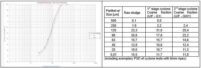 Pic 3 / Table 6: Grain size distribution, sludge PSD
Based on the performed tests and the corresponding test results, the required processing concept was evaluated. Considering the already existing process plant, an assessment was carried out in order to identify where and how the additional processing steps could be realized:
- Is an improvement of the existing plant possible?
- Could the additional steps be added to the existing plant?
After intensive investigations and discussions with the customer, a specific arrangement was agreed upon:The sludge, coming from the 3 settlers, will be directed to the new treatment installation. With the new installation 2 sludge fractions will be discharged:
- The reusable fraction, Zn reduced, that will be pumped directly to the one belt filter
- The Zn rich fine sludge, that will be directed to the thickener and treated by another belt filter
The corresponding hydrocylclone stages were developed by our experts in simulation and modelling, using the latest technologies and software to ensure a smooth operation in optimal flow within given pressure drops.
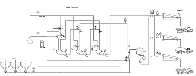
Pic 4: Flow sheet
The feed capacity, given with 3 t/h solids in 60-80 m³/h of slurry, referred to a capacity of 72 t/day of solid sludge.
In order to ensure a trouble-free operation of the hydrocyclones, the feed slurry to the treatment unit has to be pre-screened, at 2 mm, to separate misplaced coarse lumps. In order to further improve the process performances, the feed to the cyclone stage 1 is diluted with the overflow of cyclone stage 2. Also the feed to the 2nd stage is diluted with process water. The sludge with the high Zn content is directed to the existing thickener for up-concentrating and further dewatering by one belt press. The sludge with the reduced Zn content is discharged from the 2nd stage hydrocyclones and directed to the other belt press for dewatering. A third belt press is in stand-by mode. The discharge of the belt presses is falling directly to transport truck which direct the reusable fraction back to the steel plant and the Zn rich fraction for dumping.
Project Example (2)
In the year 2021 a European customer contacted us for supporting their project on blast furnaces sludge recycling and dewatering. The purpose is to design and supply, install, start, commission and warrant performances of a separation unit based on our AKA-VORTEX hydrocyclones and AKA-SET thickener technology.The project includes the segregation and dewatering of sludge containing Zn, that will afford to recycle a raw material with low content of Zn (below 0,5% concentration).The system is to be designed so as to treat undifferently different types of sludges (low and high Zn concentrated).
The tests carried out by our specialized team showed the following results:
| Parameter | Feed | 1st Stage classification | 2nd Stage classification | ||
| w/w-% | Raw sludge | Fines (O/F – F1) | Coarse (U/F – G1) | Fines (O/F- FW1) | Coarse (U/F – GW1) |
| SiO2 | 7,78 | 6,14 | 7,20 | 8,48 | 7,57 |
| Al2O3 | 2,70 | 1,97 | 2,40 | 2,76 | 2,48 |
| Fe2O3 | 38,7 | 20,5 | 39,8 | 32,2 | 41,8 |
| TiO2 | 0,11 | 0,07 | 0,11 | 0,11 | 0,12 |
| K2O | 0,42 | 0,41 | 0,35 | 0,39 | 0,35 |
| Na2O | 0,24 | <0,02 | 0,70 | <0,02 | 0,35 |
| CaO | 3,49 | 1,98 | 3,31 | 3,10 | 3,43 |
| MgO | 0,87 | 0,63 | 0,79 | 0,97 | 0,82 |
| PbO | 0,17 | 0,88 | 0,11 | 0,63 | 0,03 |
| BaO | 0,02 | 0,02 | 0,03 | 0,02 | 0,02 |
| SO3 | 3,01 | 10,1 | 2,37 | 6,24 | 1,39 |
| MnO | 0,18 | 0,10 | 0,17 | 0,14 | 0,19 |
| P2O5 | 0,12 | 0,16 | 0,11 | 0,15 | 0,11 |
| ZrO2 | <0,01 | <0,01 | <0,01 | <0,01 | <0,01 |
| ZnO | 2,17 | 13,1 | 1,70 | 7,96 | 0,47 |
| L.O.I. 1025°C | 39,9 | 43,7 | 40,7 | 36,6 | 40,8 |
Table 7: Chemical analysis
The 2-stage classification achieves a total mass recovery of 82,7 % to the U/F.
- Close to 90 % of the Fe2O3 could be recovered to the useable fraction
- The ZnO content of 2,17 % was reduced to 0,47 % in the reusable fraction
- The PbO content of 0,17 % was reduced to 0,03 % in the reusable fraction
- More than 80 % of the ZnO was separated to the fines fraction
- More than 85 % of the Pb content was separated to the fines fraction
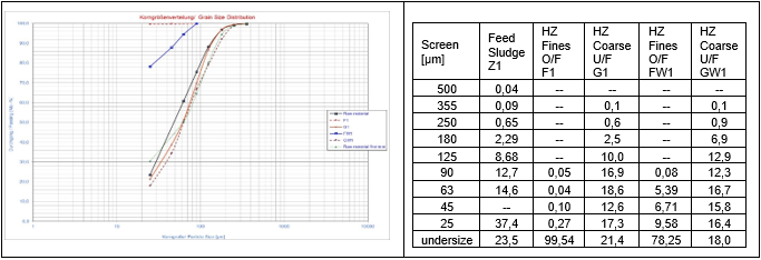
Pic 5 / Table 8: Grain size distribution, PSD of the different fraction: feed, overflows, underflows
Taking into account the above given conditions, the process set-up resulted in the following flowsheet.
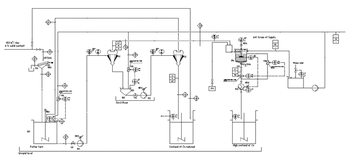
Pic 6: Flowsheet
With the given feed capacity of 650 m³/day and 8 % w/w solids content, a capacity of 52 t/day of sludge solids has to be treated by a comprehensive multi-stage hydrocycloning.
To ensure a trouble free operation of the hydrocyclones the feed slurry to the treatment unit has to be pre-screened, at 2 mm, to separate misplaced coarse lumps. In order to further improve the process performances, the feed to the cyclone stage 1 is diluted with the overflow of cyclone stage 2, therefore the feed capacity for stage 1 is considered with accordingly higher capacity. In the same way, the feed to the 2nd stage is diluted with process water in order to reach a treatable feed concentration. The sludge with the reduced Zn content is discharged from the 2nd stage hydrocyclones and directed to one of the already available tanks for further dewatering by filter press. The sludge with the high Zn content is up-concentrated by a thickener for further dewatering by filter press. The discharge of the thickener will be pumped to the second of the available tanks.
In both of the above given examples, the process control for the classification process unit was fully designed by AKW Equipment + Process Design for the continuous treatment of the sludge with:
- Level control in the pump sumps
- Automated dosing valves for the recycling flows
- Pressure control of the hydrocyclones
- Programing, control system and switchboard
Conclusion
The AKA-VORTEX hydrocyclones, made of high wear and temperature resistant polyurethane (PU), are an important addition to the blast furnace processing technology. Through customized designed multi-stage hydrocycloning concepts, the Zn concentration in a waste sludge can be significantly reduced through the generation of 2 material flows: one reusable fraction containing a reduced and acceptable Zn content, and a waste stream in which the Zn content is up-concentrated. Thanks to the high quality of the proprietary polyurethane material used in the manufacturing of the hydrocyclones, the wear occurrence is minimized, thus increasing the lifetime of the parts and accordingly optimizing the operational cost.
With AKA-SET thickeners, made out of corrosion resistant materials combined with customized coating (rubber, polyurethane or ceramic glazing), the sludge concentration is up-concentrated, for a further dewatering via belt press or chamber filter press.
As there is no standard plant concept for a BF-sludge processing unit, and as the process design and plant arrangement will primarily depend on the nature of the feed sludge, pilot test work is a perquisite to any further consideration, and in this respect constitutes for AKW Equipment + Process Design a key differentiation factor.
About us
AKW Equipment + Process Design is a medium-sized, privately owned company focused on process engineering, equipment manufacturing as well as plant construction and service. Since the foundation of AKW A+V in 1963, innovation, new product ideas and technologies have turned the company into a global operating enterprise with the headquarters in Hirschau (Germany), offices in Moscow, Shanghai and Dubai and agencies in several countries.
As AKW Equipment + Process Design is also acting as a supplier of turnkey solutions, we therefore take care from the beginning with test work, process design, equipment selection and plant design. All this completed by supervision of erection and commissioning by fulfilling the referring performance parameters.
Experience, know-how, motivation, dedication and a steadily high international standard in quality and service have turned us into a first-class partner when it comes to supporting your specific requirement – with more than 55 years of experience in minerals treatment and environmental technologies.
References
[1] World Steel Association – https://worldsteel.org/steel-by-topic/statistics/